Disclaimer | This article may contain affiliate links, this means that at no cost to you, we may receive a small commission for qualifying purchases.
Architectural symbols (drawings) are a science of their own. Just like how a scientific diagram beautifully conveys the gist of the matter, a construction blueprint also gives an overview of any given area.
When people see a construction drawing, they imagine a secure place they will spend their lives in or maybe start a business that’ll pay for their bread and butter. That’s the pathos of the matter, which undoubtedly plays a key role in the lives of people.
But if we consider the practical part of it, these blueprints become all the more important. They lay the basic groundwork for every single construction project.
Hence, it’s crucial for an architect to know his tools well, and architectural symbols are vital contributors to that. And that’s why we’ve come up with an elaborate and informational guide on the matter.
Let’s get into it!
Architectural Symbols

Understanding Scales
Architectural and construction drawings are made in such a way that all the key information about a building or property fits onto a few pages (single large spread in most cases). Therefore, they are drawn “to scale,” and a small increase in the measurements represents a much larger increment in real life.
The same scale is followed to draw each and every symbol on the legend of the floor plan. These scales vary from one plan to another and are of different complexity levels.
On a simple scale, one inch represents one foot, or another simple whole number, whereas the complex ones follow fractional proportions. A scale on which 3/16 inches represent one foot is considered to be fairly complex. 3/16, 3/4, 1/8 are other scales that are commonly used in construction drawings.
Scales give an exact idea of the configuration of all the elements in a room and are always present under the drawing or below the title for you to refer and correlate.
Different Types Of Symbols In Construction Drawings
1. Architectural Drawing Symbols
To read and understand blueprints properly, it is important to have a thorough knowledge of all the line types. The information displayed on a floorplan includes typographic features, the rights-of-way, property lines, easements, and north arrow lines.
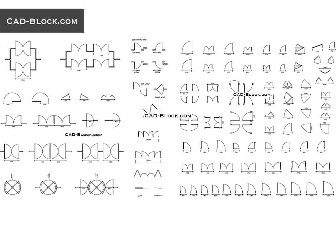
There are different symbols for different types of doors, depending on their hinges, direction of opening, number of doors, mechanism of opening and closing, etc. And the same goes for different types of windows. Double-hung, single-hung, right sash over left, left sash over right, etc., are a few common types, and each one has its own unique sign.
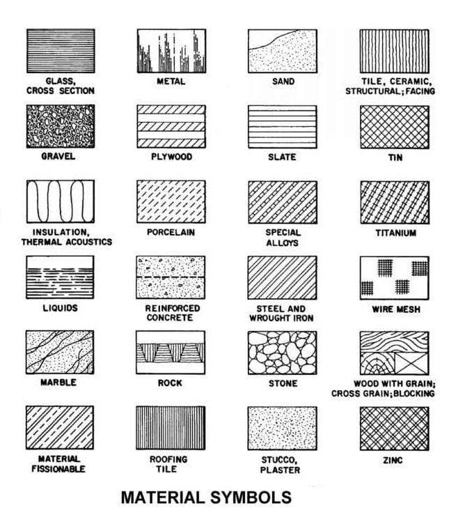
A. Material Symbols
The material symbols are a sub-category of architecture-related symbols and display the material or the content of the drawings, floor plans, or elevations. At times, different symbols can be used to depict the same material. Hence, stay clear of assuming anything and pay close attention to the symbol legend while interpreting any drawing.

Also, the same material might be represented using one symbol in section and another in elevation, so that can be a little tricky. It might give you an idea that those materials are different when in reality, it’s the same one. Want to know why these symbols differ?
It’s because the symbols draw inspiration from real life, and as you must have observed, several construction materials look different when seen from different directions. Architects and engineers take that view into account and set the symbols accordingly. For instance, a concrete block is drawn a certain way in elevated areas and some other way in sections.
However, a majority of construction components, including sand, metal, plywood, slate, marble, concrete, etc., remain the same in both views. Therefore, you need not fret too much about it.
2. Floor Plan Symbols
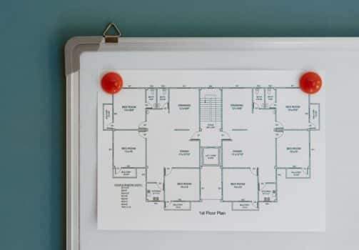
Do you know how a floor plan is drawn? Imagine that a house has been completely sliced across its walls, and you’re watching it from the top, seeing all the details of its layout. That’s just one component of the blueprint set, but it’s exactly what a floor plan looks like.

You’ll find every type of symbol, ranging from door to appliances to stairs, on a floor plan, but for the sake of your convenience, we’ll only discuss the most common ones in this section. So, some important and widely applied floor plan symbols are:
A. Compass
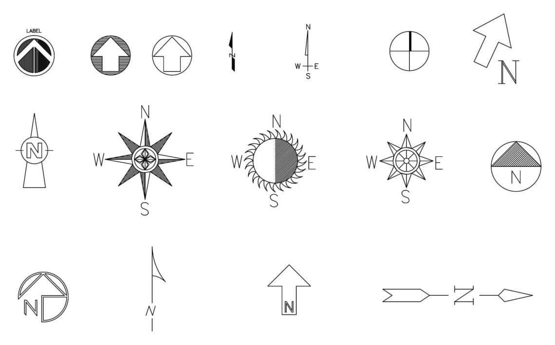
A compass, as you might have already guessed, is a symbol used for indicating directions on a floor plan and shows the orientation of a property.
Download the North Compass Symbols for Architecture.
However, it should be noted that architects and builders use “project north” as designation and the directions on a compass symbol differ from those of a real one. Meaning, you can navigate your way around the house and know all the directions without having any clue about the magnetic north.
B. Doors
We already talked a little about doors in the previous section, but we’ll elaborate a little more as they are an integral part of every floor plan. The symbols used for doors have two components: two parallel straight lines depicting the width of the door and the curved part that shows its range of motion. The curvature mainly shows the direction in which the door swings open and gives a rough idea of the clearance area.

Download the doors and windows plan CAD Blocks here.
Often a symbol, typically a hexagon, is used to number all the doors in a floor plan since there are too many. If you don’t number them properly, chances are you will lose the count and make things sloppy.
C. Windows
While doors and walls are denoted with double lines, a window is indicated using three parallels. Just like hexagons are used for numbering the doors, numbered diamonds display the window schedule of a property.

While looking at a floor plan, you will come across certain abbreviations elaborating on the window. For instance, EQ stands for equal describing of the dimensions of the window so that you understand the plan better. A ‘C’ with an ‘L’ passing through its center denotes that the window has equal space on each side and is centered.
D. Stairs
When it comes to floor plans, the stair symbols are the easiest to identify as they are simply two parallel lines running consecutively across the drawing. Needless to say, like all other symbols, stairs also follow the measurements specified by the scale.
E. Walls
A layperson would think that walls are simple and can ideally be depicted using a single line, but we’re afraid that’s not how it works. Walls are drawn by following certain norms to avoid all sorts of confusion and help you understand the floorplan better.

If you look at a good drawing, you’ll easily be able to distinguish between walls and other components and demarcate the exterior walls from the interior. Single lines are used for displaying the interior part of the walls, while external walls are drawn as thick and weighty double lines.
F. Appliances
Fixtures and appliances like sinks, bathtubs, toilets, etc., are drawn using a fine line and resemble the structure that they represent. You must have seen toilet seats or basin illustrations in the brochure or floor plan of an apartment; that’s exactly what we are referring to!

Download the appliances CAD Blocks here.
In similar lines, light line weight is used for denoting furniture and other appliances so that you understand at first glance that these figures aren’t structurally integral for the property. They are just displayed to give you a hands-on idea of the dimensions of the room and how it is intended to be set.
Dotted lines are used to draw microwaves and cabinets to make sure that they don’t draw too much attention, and you focus on the other important architectural elements. You see, construction drawings have many layers to them.
3. MEP (Mechanical, Electrical, and Plumbing)
The MEP plans are an extension of the floor plan of a property and are delivered as a blueprint bundle separately. They are made using appropriate mechanical, electrical, and plumbing symbols and are a little more complicated than the basic architectural plans.
These professional blueprints display the exact locations of various fixtures and routes of the connection lines. As a framer, you’re expected to know where the MEP systems are routed in a property so you can plan out the interior accordingly, leaving spaces for the outlets. This is the primary function of MEP drawings.
Let’s discuss these plans in detail:
A. Electrical Symbols
Electrical drawings should only be prepared by competent drafters with electrical expertise to avoid unnecessary errors and delays. Electrical symbols are used to simplify the work for both the planners and the engineers interpreting the drawings. However, these signs and symbols aren’t uniform all across the industry, and that’s why a drawing involving electrical symbols usually contains symbol legend.

Download the Electrical Symbols CAD Blocks here.
Lightening arrangements can effectively be shown with the help of symbols; do you want to know how? We’ll tell you in detail.
The switch symbols are drawn perpendicularly to the wall and are read from right to left or from the bottom. The electrical construction drawing for a small land or property usually includes wiring and small devices like receptacles, appliances, light fixtures, and switches. It is basically a blueprint that indicates which light is connected to which controller.
The receptacles and outlets are typically displayed in their estimated positions, while major appliances and fixtures are indicated in their proper places. The list also contains abbreviations for certain terms like WP for weatherproof, TV for television outlet, etc.
You’ll notice that most signs are a combination of elementary geometric figures designed in a way that is easy to pen down or comprehend. But since there are so many of them, it gets complicated over time, so a symbol legend is crucial.
So, one efficient way to memorize these symbols is by learning their primary forms, like a square or a circle. Once you master them, you can move on to the complicated ones that mainly contain some lines, figures, or structures in addition to the fundamental structures.
B. Plumbing Symbols
The water-carrying systems differ for different industries and can be classified mainly into three categories: residential, commercial, and industrial.
The piping systems used for residential and commercial purposes generally carry water, solid and liquid wastes, and gases and are called “plumbing.” Since there isn’t any involvement of toxic or hazardous wastes, these pipes are made of copper, cast iron, galvanized steel, or plastic.

Download the Plumbing Fixtures and Fittings CAD blocks here.
In contrast, industrial-grade pipes are engineered to transport heavy gases and liquids utilized in manufacturing. In fact, the steel pipes are modified with threaded or welded connections in the construction sector.
Piping drawings are made using plumbing symbols to simplify the construction for everyone and save some time along the way. All the fixtures, pipe-fittings, valves, and several other components are showcased using plumbing symbols. To give you a better picture, we’ll tell you about a few of these graphic symbols, so stay with us and keep reading.
A simple pipe is represented by a single line corresponding to the shape of the pipe (it can be straight or curved). This is the basic structure, and most other types of pipe will merely be its modifications. For example, add two small vertical lines, and you’ll get the symbol for a joint-flanged, whereas adding a single will give you the sign for a screwed pipe. Interesting, isn’t it?
Similarly, there are tons of symbols corresponding to different fixtures and pipes that are used in plumbing drawings. Most are simple, while some like reducing or enlarging fittings and reducer concentric get a little twisted and require revisions.
C. Mechanical Symbols
These symbols are used to denote mechanical aspects in a construction drawing and can further be divided into several other categories. We’ll discuss each of them one by one.
I. Heating, Ventilation, and Air-conditioning Symbols (HVAC)
The main motive of HVAC symbols is to showcase the position of cooling, heating, and air conditioning units with respect to the duct and plumbing diagrams. These graphic symbols include a few from the plumbing and electrical categories as they cover both these aspects.

Download the Mechanical HVAC Symbols blocks here.
Mainly two types of symbols can be seen in these systems, the main lines, and the subordinate branching lines. The main ducts are drawn with heavy line weight or a rectangle depicting its actual shape, while the branches are represented by single lines. The dimensions are mentioned adjacent to these lines to make it easier for you to visualize the space taken up by these elements.
II. Fire Alarm System Symbols
The next category in the mechanical symbols is the fire alarm systems, but we won’t go much into the details as they can best be understood by pictorial representation. A few common fire alarm symbols are used for smoke detector duct type, terminal cabinet, alarm transmitter, supervisory valve switch, electromagnetic type door holder outlet, and many more.

4. Reflected Ceiling Plan (RCP)
Builders use Reflected Ceiling Plans to display the materials, dimensions, and other crucial information related to the ceiling of all the rooms present on the property blueprint. By the way, the plan’s name is quite interesting, don’t you agree? Do you know why it’s called so? We’ll get back to that part after discussing its importance and utility. Stay tuned!

Download the Reflected Ceiling Plan Symbols Legend here.
A ceiling blueprint essentially portrays the details of the ceiling, including the material used for its construction. As we discussed at the beginning of our guide, material symbols display the raw material used in the construction and are used for representing not only flooring but ceilings too.
Next, an RCP contains symbols that show the height and other dimensions of the roof. So basically, you can find out everything you need to know about a ceiling simply by looking at this plan. It also shows the alignment and layout, and occasionally some ornamentation too.
Now, coming back to the name as promised. A Reflected Ceiling Plans looks as if you were looking at the roof as reflected by a mirror placed right below it on the floor. And that is exactly the reason why it’s known as a “reflected” plan.
5. Miscellaneous Symbols
There are thousands of symbols in the architecture industry and to name and categorize all of them simply isn’t possible. Additionally, half the symbols are standardized, while the other half is industry-driven and follows different institutional standards.
We’ll cover those ambiguous symbols in this section:
A. Component Symbols
Component symbols are those accessory symbols that don’t play a crucial role in the structure of a property and are just used for reference purposes. These include illustrations of fixtures like sink, bathtub, toilet, etc., and furniture pieces.
Even if you take out these symbols, the structural integrity of your construction drawing wouldn’t be affected much. They are just there to give an idea of the spatial dynamics of the room; for example, you’ll get a clear picture of how much floor space is there if you see a scaled drawing of some furniture piece kept in that area.
Apartment blueprints often include component symbols like microwaves, coffee tables, ACs, etc., to give the potential customers an idea of the area. It’s also a good demonstration of how to design and arrange furniture in specific rooms.
B. Specialist Symbols
Certain specialist trades like communication and welding have their own specifically designed symbols that cater to their special needs. We’ll explain that with the example of the welding industry.
There are several types of welding, and to effectively show them into a drawing, the people of the industry have devised their own symbols. A cross-hatch is used to depict a seam weld, while a single vertical line denotes a flash, and so forth.

Final Words
We’d like to wrap up for the day with a few quick tips and tricks. You’ve already mastered the topic by reading this plethora of knowledge, but a few finishing strokes never hurt anyone, right?
So, to summarize, remember that these blueprints aren’t set in stone, and there is always some scope of adjustment if things don’t seem to be working out. The position of symbols on elevations or floor plans can be approximate if they aren’t dimensioned.
Furthermore, symbols vary in size depending on the scale of the drawing, and you should be attentive and collect accurate information while scaling them. Just stick to these small rules, and you’ll be good to go.
And with that, we’ve reached the end of our guide on architectural symbols. Hope you found it informative and worthy of your time!
Related Links
Architectural Drawings From the World’s Greatest Architects
11 Delightfully Absurd Architectural Drawings
Architecture or Achiterror | 13 Challenges Every Architect Faces Today
Drawing Architecture by Phaidon | Architecture Ideas and Concepts Illustrated
The Evolution of Architectural Design: From Drawings to Digital Concepts
MoMA Offers Japanese Navigators in an Architectural Firmament
Draw Like an Artist | Buildings & Architectural Forms by David Drazil
Cairo since 1900 | An Architectural Guide by Mohamed Elshahed
17 Best Landscaping Design Software [Free & Paid]
Best Gifts for Architects [Gift Guide]
30 Best Architect Lamps for Desk, Table & Office


