The Importance of Earthing Systems in Protecting People and Equipment from Electrical Shocks
Earthing systems (grounding systems) are a critical component in electrical installations, ensuring the safety of both individuals and equipment by preventing dangerous electric shocks and minimizing damage caused by faults or surges. This article explores the concept of earthing, its main types such as TT and TN-C systems, methods for measuring and reducing earth resistance, and best practices to maintain safe and effective grounding.
What is Electrical Earthing?
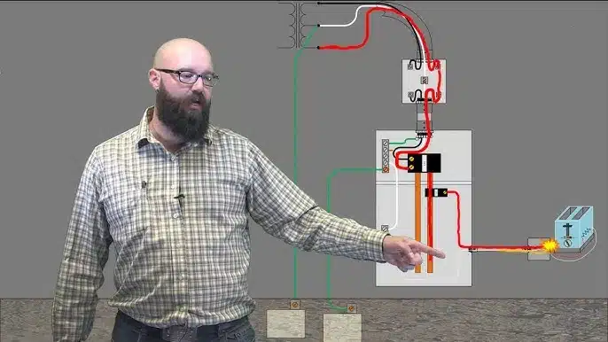
Electrical earthing refers to the process of connecting specific parts of an electrical circuit or system to the ground through conductive materials. The primary purpose of earthing is to safely divert excessive or fault currents into the earth, protecting people from electric shocks and preventing equipment damage. It also helps stabilize voltage levels and ensures proper operation of protective devices like circuit breakers and fuses.
Main Types of Earthing Systems
There are several earthing systems, each with distinct configurations and applications. Two of the most commonly used systems are:
| System | Description |
|---|---|
| TT System (Terra-Terra) | In this system, the power source and the electrical installation are separately connected to the earth. It is commonly used in standalone buildings and rural areas. |
| TN-C System (Terra-Neutral Combined) | Combines the neutral (N) and protective earth (PE) functions into a single conductor (PEN) throughout the system. It is often found in older installations but offers lower safety compared to more modern systems like TN-S. |
Each system has advantages and limitations, and selection depends on local regulations, installation type, and safety requirements.

Why Measuring Earth Resistance is Important
Earth resistance is a key indicator of the effectiveness of an earthing system. Lower resistance values mean better conduction of fault current into the ground, enhancing safety. Resistance is typically measured using specialized instruments such as an earth tester or through the three-point fall-of-potential method.
Acceptable Earth Resistance Values:
| Application | Acceptable Value |
|---|---|
| Distribution substations | Less than 1 ohm |
| Residential buildings | Less than 25 ohms |
| Sensitive electronic equipment | Less than 5 ohms |
Regular measurement ensures that the system remains within safe limits and continues to function effectively over time.

Methods to Reduce Earth Resistance
If resistance measurements exceed acceptable limits, engineers can apply several techniques to enhance grounding performance.
- Increasing the Number of Earth Electrodes:
- Installing multiple electrodes in parallel or triangular arrangements increases surface contact with the soil.
- Using Chemical Enhancements:
- Adding conductive materials such as sodium chloride or bentonite clay improves soil conductivity.
- Deepening the Earth Electrode:
- Extending the electrode to deeper, more moist layers of soil reduces resistance.
- Installing a Ground Grid:
- A network of interconnected conductors buried underground provides extensive grounding coverage.
Engineers should select appropriate grounding methods based on site-specific conditions and soil resistivity tests

Frequently Asked Questions (FAQ)
| Question | Answer |
|---|---|
| What is the difference between earthing and bonding? | Earthing connects equipment to the ground; bonding connects metallic parts together to eliminate potential differences. |
| Can steel rods be used for earthing? | Plain steel corrodes easily; copper-bonded or galvanized steel rods are preferred for durability. |
| When should earth resistance be retested? | Annually, or after any major modifications to the system or surrounding environment. |

Summary Table of Key Points
| Point | Details |
|---|---|
| Definition | Connecting electrical systems to the earth for safety |
| Main Systems | TT, TN-C |
| Importance of Measurement | Ensures system effectiveness and safety |
| Acceptable Values | Vary from 1 to 25 ohms depending on application |
| Improvement Methods | Multiple electrodes, chemical treatment, depth increase, ground grids |
ArchUp Opinion
Earthing systems form the foundation of electrical safety, yet engineers and project managers often overlook them during design and maintenance, particularly in small-scale or less-regulated projects. One common issue is the lack of regular inspection and testing, which can lead to degradation over time due to corrosion, soil drying, or physical damage. Organizations must prioritize training engineers and technicians to ensure the long-term reliability and safety of earthing systems. Adherence to international standards such as IEC 60364 and IEEE Std 80 is essential to ensure consistent and reliable protection across different applications.


